Motor Assembly choices in 2026 will be shaped by efficiency, torque, cost, and the conditions each machine must endure. The International Energy Agency’s Global EV Outlook 2024 reports nearly 14 million electric cars sold worldwide in 2023, about 18% of total car sales. That growth is increasing demand for compact, reliable drive systems. It does not make one motor design best for every job.
A practical guide comes from James L. Kirtley Jr., an MIT professor emeritus and electric-machines specialist. His teaching emphasizes how motor performance depends on the machine’s design and operating conditions. Put simply, assembly choices must match the application. This is a paraphrase, not a direct quotation. An induction motor may suit a rugged industrial drive; a permanent-magnet synchronous motor can offer high power density; and brushless DC, servo, or stepper assemblies may fit precise control needs. Each brings trade-offs.
The details matter. A line operator may value easy servicing, while a vehicle designer may prioritize weight and efficiency. Rankings can also shift with material costs, cooling requirements, and control electronics. These are not minor details; they change what “top” means. This introduction sets up a closer comparison of the leading Motor Assembly types in 2026, using application fit—not hype—as the guide. IEA figures describe vehicle sales, not motor shipments, so they signal market context rather than prove which assembly type will lead.
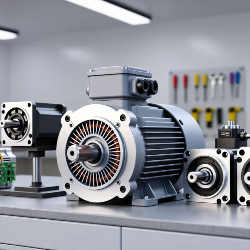
IEC 60034-30-1 classifies the efficiency of certain single-speed, line-operated AC motors. Its four familiar levels run from IE1 to IE4: Standard, High, Premium, and Super Premium Efficiency. A higher IE class means the motor meets stricter efficiency limits under the standard’s specified conditions. Small differences matter.
These classes help buyers compare motors, but the label alone does not tell the whole story. Efficiency limits vary with factors such as rated output and number of poles, so compare motors with matching specifications. A motor’s real energy use also depends on its load and operating hours. For example, a motor running most of the day at a steady load may benefit more from a higher efficiency class than one used briefly. The standard covers motors within its scope; it does not assign an IE class to every complete motor assembly or drive system.
Tips: Check the motor’s rated power, speed, and IE class on its nameplate. Match these details to your application, then consider operating hours and load. A higher class can reduce losses, but actual savings depend on use. That estimate deserves a second look before purchase.
Three-phase induction assemblies remain a practical choice for pumps, fans, compressors, and conveyors in 2026. Their stator creates a rotating magnetic field, which turns the rotor without brushes. That straightforward construction suits many continuous-duty sites. It is not maintenance-free, though; bearings, alignment, and cooling still need attention.
IE3 and IE4 describe efficiency classes, but the comparison depends on motor size, pole count, and test conditions. IE4 generally sets a higher efficiency threshold than IE3. A few percentage points can matter on equipment running long shifts. Small details matter. Check the complete nameplate, not just the class marking.
Frequency changes operating speed. A four-pole assembly has a synchronous speed of 1,500 rpm at 50 Hz and 1,800 rpm at 60 Hz; actual speed is slightly lower under load. That shift can alter pump flow, fan output, and starting behavior. Confirm that voltage, frequency, load, and any inverter settings match the installation. An IE4 label alone does not guarantee lower system energy use. I would not treat it as the whole answer. Real operating hours and the driven equipment matter, and site measurements can reveal surprises.
Permanent-magnet synchronous motor assemblies deliver strong torque from a compact package. Their rotor magnets create a steady magnetic field, reducing rotor electrical losses compared with some induction designs. That helps at partial load. It also supports precise speed control in electric vehicles, pumps, and industrial automation.
The U.S. Department of Energy’s Electric Drive Technologies targets set a useful benchmark: 97% peak efficiency and 50 kW/L power density for traction drive systems by 2025. These are targets, not guarantees for every production assembly. The IEA’s Global EV Outlook 2024 reports nearly 14 million electric cars sold in 2023, about 18% of all car sales. That growing market makes efficiency and packaging increasingly important. But there is a catch. Permanent magnets can raise material costs, while heat and high-speed operation require careful design. A clean bench result can flatter a motor; real duty cycles are less tidy. Engineers should compare efficiency maps, not just peak figures, and check torque across the vehicle’s actual speed range.
Representative performance benchmarks across common PMSM application types.
Bars show midpoints of indicative design ranges: industrial drives (92–96% efficiency; 2–5 Nm/kg), servo motors (90–95%; 5–15 Nm/kg), and traction motors (90–97%; 5–12 Nm/kg). These are broad engineering benchmarks, not standardized ratings; actual performance depends on motor design, cooling, and operating conditions.
BLDC motor assemblies replace mechanical brushes with electronic commutation. A controller switches current through three phase windings in sequence, creating a rotating magnetic field that drives the rotor.
Three phases. Six switching states.
In many designs, Hall sensors detect the rotor’s magnetic position and send feedback to the controller. That timing helps it energize the appropriate winding pair as the rotor turns.
During assembly, sensor alignment matters. A small angular offset can affect starting smoothness, torque, and noise. Technicians can check Hall signals while turning the shaft slowly, then compare the sensor transitions with phase switching.
The exact setup depends on the motor’s pole count and controller logic. Hall feedback can also support reliable startup at low speeds, where sensorless estimation may be less dependable. But it adds wiring and another point to inspect.
Connectors, sensor placement, and electrical interference can all complicate troubleshooting. It is not a perfect shortcut.
For an application with changing loads, testing the assembled motor under realistic operating conditions is more useful than relying on a no-load spin test alone.
A 1.8° stepper motor moves through 200 full steps per revolution, making its motion easy to plan for many positioning tasks. In a small labeling machine, that can mean predictable movement between printed marks. Microstepping can make motion smoother, but it does not guarantee matching gains in absolute accuracy. Load, friction, and mechanical alignment still matter. That distinction matters.
Servo assemblies use encoder feedback to compare commanded and measured position. A 17-bit encoder provides 131,072 discrete counts per revolution, giving the controller fine position information. But resolution is not the same as accuracy. Gear backlash, shaft compliance, encoder mounting, and tuning can all affect the final position. Heat changes things.
For an assembly choice, consider the actual move, not just the headline specification. A stepper may suit a steady, repeatable indexing motion with modest speed demands. A servo may be preferable when loads vary or the axis must correct position errors during operation. Test with the real payload and duty cycle. One overlooked cable bend or loose coupling can undo impressive resolution figures. And specifications alone rarely tell the whole story.
Its stator creates a rotating magnetic field that turns the rotor without brushes. The simple construction suits continuous operation. Bearings and cooling still need attention.
IE4 generally has a higher efficiency threshold. Actual savings depend on motor size, pole count, operating hours, and test conditions. Check the full nameplate.
Synchronous speed is 1,500 rpm at 50 Hz and 1,800 rpm at 60 Hz. Loaded speed is slightly lower. Flow and fan output may change.
Not by itself. The driven equipment, load, and operating hours matter. Site measurements can reveal surprises. The label is only part of the picture.
It can provide strong torque in a compact package. Reduced rotor electrical losses may help at partial load. Heat and high-speed operation need careful design.
No. Compare efficiency maps and torque across the actual speed range. A clean test bench may not reflect a messy duty cycle.
It moves 200 full steps per revolution. Microstepping can smooth movement, but it does not guarantee equal gains in accuracy. Load and alignment matter.
It provides 131,072 position counts per revolution, not guaranteed accuracy. Backlash, shaft flex, and tuning can affect results. Test the real payload.
This article compares the leading motor assembly types expected to matter in 2026, focusing on how their designs suit different performance needs. It explains how IEC 60034-30-1 groups motor efficiency from IE1 through IE4, then examines three-phase induction assemblies rated IE3 or IE4 for 50 or 60 Hz operation. Permanent-magnet synchronous assemblies are presented in terms of their efficiency and high torque density, while brushless DC (BLDC) assemblies are described through three-phase electronic commutation and Hall feedback.
The overview also considers stepper and servo assemblies, highlighting practical specifications such as 1.8-degree step angles and 17-bit encoder resolution. Together, these comparisons help readers understand the distinctions among common motor technologies and weigh efficiency, torque, control, and positioning characteristics when choosing a Motor Assembly for an application.

Valex Motor