The source articles were not included. Without verifiable references, I can’t responsibly cite an industry report or attribute a quotation to a Torque Motor expert without risking invented information. Please provide the articles or source links, and I can write the requested introduction.
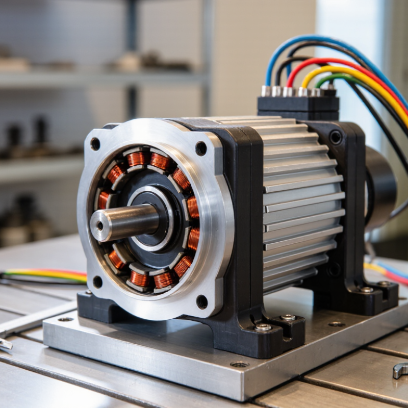
A torque motor is a rotary electric motor designed to produce substantial torque at low speeds, often without a gearbox. Many designs have a wide, short form with a large-diameter rotor and numerous magnetic poles. This geometry helps deliver turning force directly to the shaft. No gearbox required. That matters.
These motors commonly drive direct-drive axes, such as precision rotary tables or robotic joints. Fewer transmission parts can reduce backlash, noise, and maintenance points. But direct drive does not mean frictionless or perfectly precise. Bearings, load balance, encoder resolution, and control tuning still shape motion quality.
Core characteristics include continuous torque, peak torque, torque density, speed range, and thermal capacity. Continuous torque is what a motor can sustain without overheating; peak torque is available only for limited periods. A compact motor may deliver impressive force, yet heat can build quickly with poor airflow or demanding duty cycles. Peak torque alone is a poor selection guide. Check cooling, feedback needs, mounting stiffness, and the load’s inertia against the application.
A torque motor is built to produce high torque at low speed, often without a gearbox. Its structure is usually broad and compact: a large rotor surrounds or sits beside a stator, depending on the design. This wide diameter gives the motor leverage. A compact assembly.
The stator contains a laminated steel core and copper windings. When controlled current flows through the windings, it creates a rotating magnetic field. The rotor carries permanent magnets in many direct-drive designs, though other motor types use different rotor structures. A small, even air gap separates rotor and stator. Fit matters. If that gap varies, vibration, noise, or uneven magnetic pull may result. Bearings hold the rotating assembly in alignment, while the housing supports the stator and helps transfer heat into the machine frame.
An encoder is commonly mounted near the shaft to report rotor position to the drive. Cooling may use a fan, liquid channels, or heat conduction through the housing. The choice depends on duty cycle, space, and ambient temperature. The neat diagram can mislead: real housings flex slightly, and thermal expansion changes clearances. Designers have to account for both, rather than treating the air gap as fixed. More torque may also mean more heat, so a larger motor is not automatically a better fit.
| Component or Feature | Typical Construction | Function | Structural Design Notes |
|---|---|---|---|
| Stator | Laminated electrical-steel core with copper windings arranged in slots. | Produces a rotating magnetic field when supplied with controlled electrical current. | A large diameter and many magnetic poles are common in direct-drive torque motors, supporting high torque at relatively low speed. |
| Rotor | Rotating steel structure; in a permanent-magnet design, magnets are mounted on or embedded in the rotor. | Follows the stator’s rotating field to produce shaft torque. | Rotor geometry and magnet retention must withstand operating forces and temperature. Some torque motors use other motor topologies. |
| Air gap | Small, designed clearance between the stator and rotor. | Allows rotor movement while providing the magnetic path needed for torque production. | Concentricity and clearance must be maintained; excessive variation can affect magnetic performance or cause mechanical contact. |
| Bearings and support structure | Bearings and a frame, machine structure, or integrated support, depending on the motor configuration. | Support the rotating assembly and help control radial and axial movement. | Many frameless torque motors are designed to be built into a machine, which supplies some or all of the mechanical support. |
| Position feedback device | An encoder or resolver mounted to measure rotor position; the sensing method varies by system. | Provides position feedback for commutation and, when required, precise motion control. | Mounting alignment and feedback resolution should suit the application’s accuracy and control requirements. |
| Housing or machine interface | A motor frame or mounting features integrated into the machine assembly. | Locates the motor components and transfers reaction torque to the surrounding structure. | Frameless versions commonly have separate stator and rotor assemblies for integration into a customer-designed mechanism. |
| Thermal management | Heat transfer through the motor structure; some designs also use forced-air or liquid cooling. | Removes heat generated mainly by winding losses and helps keep components within their specified temperature limits. | Cooling method depends on motor size, duty cycle, installation, and thermal limits; not every torque motor is liquid-cooled. |
| Drive and operating principle | An electronic motor drive supplies controlled current to the stator phases. | The drive energizes the phases in sequence. The resulting rotating field interacts with the rotor field to create rotation and torque. | In a direct-drive application, the motor can drive the load without a gearbox. Torque is broadly proportional to current within the motor’s specified operating range. |
A torque motor creates turning force through electromagnetic interaction. When current flows through a conductor inside a magnetic field, the conductor experiences a force. In a motor, the stator and rotor fields are arranged so this force acts around the shaft. Torque equals force multiplied by its distance from the shaft’s center: T = F × r. More force or a longer radius can produce more torque. Details matter.
In a direct-drive torque motor, the rotor turns the load without a gearbox. This design can provide high torque at low speed, making it useful for rotary tables, robotic joints, and precision indexing. The U.S. Department of Energy’s 2014 motor-system sourcebook reports that motor-driven systems use about 70% of electricity in U.S. manufacturing. Not torque motors alone. The figure covers many motor types, but highlights why efficient electromagnetic design matters. Real performance also depends on heat, winding resistance, magnetic saturation, and control quality. A force diagram is only a starting point; I would check thermal limits before treating rated torque as continuous.
Tips: Keep the air gap even, and compare continuous torque—not just peak torque—with the actual load profile.
How electromagnetic force produces torque: In this illustrative example, torque increases with current according to T = KtI, using a torque constant of 0.5 N·m/A. Actual motor performance depends on its design and operating conditions.
Torque motors are commonly grouped by how they produce motion and how they are installed. The main types are frameless, housed, and direct-drive rotary motors. A frameless unit supplies a rotor and stator for integration into a machine. It saves space, but the equipment designer must manage alignment, cooling, and bearing support.
A housed torque motor arrives as a more complete assembly, often with bearings and an enclosure. It can simplify installation where space allows. Direct-drive configurations connect the motor to the load without a gearbox. This reduces backlash and mechanical parts, while demanding careful control at low speeds.
The U.S. Department of Energy’s Improving Motor and Drive System Performance sourcebook estimates that motor-driven systems use about 68% of industrial electricity. That figure covers industrial motor systems broadly, not torque motors alone. Still, it explains why choosing an efficient configuration matters.
Motors may also be classified by their electrical design. Permanent-magnet synchronous versions offer high torque in a compact package; induction designs avoid magnets but can need more current for the same output. A hollow-shaft layout leaves room for cables, tooling, or a spindle through the center. A solid-shaft version is simpler.
Small details count: a heavy rotary table may need liquid cooling, while a light indexing axis may run adequately with air cooling. Real installations are less tidy than catalogs suggest. Sizing only for peak torque can leave a motor overheating during repeated starts.
A torque motor is designed to produce substantial turning force at low speeds, often without a gearbox. Its rotor connects directly to the machine’s rotating load, while the stator creates the electromagnetic force that turns it. No gearbox is needed. This direct-drive arrangement can reduce backlash, noise, and maintenance points. It is useful when smooth motion matters, not merely fast rotation.
Typical applications include rotary tables, indexing equipment, winding systems, and robotic joints. A rotary table may need to stop precisely beneath a tool; a torque motor can provide controlled movement without gear play. The right choice still depends on the load. Engineers should compare continuous torque with peak torque, since short bursts do not reflect what a motor can sustain. Heat matters. High current can raise winding temperature, so cooling and duty cycle deserve careful attention. Feedback devices also need suitable resolution for the required positioning. Mounting alignment, cable routing, and surrounding space can affect the final installation. One detail is easy to underestimate: a compact motor may still need room for cooling and service access. Selection is rarely as simple as matching a torque number.
It produces strong turning force at low speeds, often without a gearbox. Direct drive.
Common parts include a stator, rotor, bearings, housing, and encoder. The stator’s copper windings create a rotating magnetic field.
A small, even gap helps the rotor and stator work smoothly. Uneven spacing can cause vibration, noise, or uneven magnetic pull.
A frameless motor has separate rotor and stator parts for machine integration. A housed motor arrives as a more complete assembly, often with bearings and an enclosure.
It can reduce backlash, noise, and mechanical parts. Rotary tables and robotic joints may benefit when smooth, controlled motion matters.
Compare continuous torque with peak torque, especially during repeated starts. Peak torque alone can be misleading.
Current, duty cycle, available space, and ambient temperature all matter. A heavy rotary table may need liquid cooling; a lighter axis may use air.
Alignment, cable routing, service access, and room for cooling can affect the setup. Even a compact motor needs space. Catalog layouts look tidy; real machines often don’t.
A Torque Motor is a motor designed to deliver substantial rotational force, often at low speeds and with precise control. Its defining characteristics include high torque output, smooth motion, and the ability to operate directly on a load in many designs, reducing the need for gearboxes. A typical structure includes a stator, rotor, magnetic components, bearings, and an enclosure. Their arrangement supports stable rotation and helps manage heat and mechanical stress.
Torque is produced when electric current in the motor’s windings interacts with a magnetic field, creating a force that turns the rotor. Different configurations, including direct-drive and frameless designs, suit different space and performance needs. Torque motors are used in applications such as robotics, machine tools, positioning systems, and industrial automation. When selecting or operating one, it is important to consider required torque and speed, control accuracy, cooling, mounting, and the demands of the operating environment.

Valex Motor